

| |
|
|
|
|
|
|
$1 Wireless InterfacePublished in Circuit Cellar Magazine, Feb 2004.Want a wireless interface for your next project? Got some wire? With a coil, a cap and a transistor, you can make your next project emulate a Radio Frequency Identification Device (RFID), commonly called a "tag" or an "RFID tag." Here's how... RFID OverviewThe RFID industry has been in the news this year with big support from Gilette, WalMart and the DoD. With that heavy money lined up, the technology is poised to take off. Widespread adoption of RFID will have effects beyond the RFID industry itself. People are already discussing RFID tags as the leaf nodes in an "internet of things," suggesting that RFID is also poised to generate a flood of data, driving sales of routers, storage, and processing capacity in an effort to keep up. The Internet holds a growing body of RFID information. One good place to start reading is https://www.rfidjournal.com .In general, RFID systems follow a simple model. A device usually called a "reader" creates a field. One or more tags communicate with the reader by varying the amount of energy reflected back to the reader by the tag. This process is called "backscatter," and it's the really neat thing about RFID technology, enabling very cheap devices to communicate by wireless. 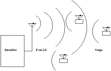 What's in a Tag?The general mechanism for creating backscatter is to detune a tuned element. The tuned element can be a resonant circuit or a dipole antenna, depending on the tag's frequency range - more on that later. The point is this - your tag can be tuned, or it can be detuned, without creating much of a stir. But when the tag changes from one state to the other, it creates a disturbance in the field. A well timed series of such disturbances starts to look like a datastream. An RFID tag contains the minimum possible circuitry needed to produce that datastream: the antenna itself, a diode and capacitor to scavenge power from the field, another diode or transistor to detune the antenna, and a little intelligence.There are many types of RFID tags. Some fill unique market niches, some embody really cool technology. And some are just there because somebody thinks they can make a buck on them. The different tag types can be divided in a few ways. The most useful ways are Passive vs. Active, Tag Talk First vs. Reader Talk First, and by Frequency Range. Passive vs. ActiveMost of the time, when people talk about passive tags, they mean tags that get their power entirely from the RF field generated by the reader. The same people use the term "active tag" to mean tags that get their power from a battery and use the reader's field only for communications. But that's not technically correct, and it fails to cover some of the most economically important devices. The correct usage of the terms is this: passive tags communicate by backscatter, so a tag can be "passive" even if it has a battery backup. Active tags do not use backscatter, but incorporate low power radios something like radar IFF systems. Of course, active tags need a battery or other power source - they cannot scavenge enough power from the reader's field to run that radio.The California company Savi has an active tag, readers and LAN protocol that together provide a complete vertical solution for tracking shipping containers. Savi's big application is military shipping containers - they were tried out in the first Gulf War, and now every container bound for Iraq and Afghanistan is identified with a Savi active tag. For another application, most RFID based toll payment systems work with active tags. Active tags are inherently more expensive than passive tags - at the moment - because of the battery. But that gap is closing, too, as the difficulties of passive antenna design and bonding tag silicon to antenna take center stage as the most expensive aspects of producing tags. The biggest commercial application for passive tags is car immobilization. The large plactic knob at the end of new car keys typically holds a passive tag. The embedded computer of cars equipped with this kind of system will not allow the car to be started or driven unless it sees data it recognizes on the key's RFID tag. Each car company has its favorite tag, but the market leader is MicroChip, the company that brings us the PIC processor. Another familiar application is the key fob that lets you buy gas and fast food without pulling out your credit card. Who Talks FirstThe RFID world has intermittent religious wars over which component of the system should talk first - the reader or the tag. Readers typically communicate with tags by creating timed gaps in the field. The gaps have to be long enough to be sensed at a distance, but short enough that tags do not lose power during the gap interval. Most tags wait for a command - a series of gaps - from the reader before modulating the field. These are known as "reader-talk-first" tags. Some tags, however, start modulating as soon as they power up (or in the case of active tags, as soon as they detect a reader's field). These tags are known as "tag-talk-first" tags. Each approach has its own strengths and weaknesses, but it's obvious that tag-talk-first is the simplest approach, and it's the one we'll be using in this demo project.Frequency RangeIn the USA, RFID operates in four frequency bands set aside for Industrial, Scientific and Medical (ISM) purposes. Although the terms have other meanings, within the RFID industry the terms LF, HF, UHF and Microwave are used as shorthand for the ISM bands used for RFID in those larger regions of the spectrum.
Outside the USA, the bands differ slightly, mainly in the UHF range. European UHF is defined in the middle 800 MHz range, and in Japan UHF is higher in the 900 MHz range. Other countries also have different rules for hopping, duty cycle, power and bandwidth. LF and HF tags couple to the readers inductively, using coils as antennas, and enabling the readers to be very simple electrically. UHF and MW tags couple radiatively, requiring more complex reader electronics but providing more range in return. Overview of the Atmel 5551 Air InterfaceYou can add a very cheap wireless interface to your next project by making it act like an RFID tag. The Atmel 5551, a tag-talk-first passive tag, is the tag best suited to this application for a few reasons:
The default behavior of the Atmel 5551 is to backscatter its data on the air interface whenever it is energized by the field from a reader. So, you can set up your hardware to continually backscatter the data you want to transmit. If a reader is there, the data will be transferred. If no reader is there, then you are not losing anything beyond a few compute cycles. The Atmel 5551 has many configuration options. You don't have to worry about handling all the configurations. Just pick one, and set up your system to emulate that. Referring to the tag's configuration word on page 5 of the data sheet, you want to emulate a Manchester tag with Sequence Termination, running at 128 cpb. You can emulate a MAXBLOCK of 1 through 7 based on how much data you want to handle. In the language of low frequency tags, "cpb" stands for (carrier) cycles per bit. At 125 KHz carrier, each cycle takes 8 uS, so 128 cpb translates to 128*8 uS, or a millisecond, per bit. Why so slow? Couple of reasons. First, a slow interface minimizes the impact on your project's compute cycles. Second, slow transitions on the air interface are easier to detect, which means you will have more range and more reliable communications. Finally, the reader used to verify this design reads the Atmel tag configured this way by default, and requires no setup commands to do so. We can skip over the question of how to modulate bits onto the air interface, and go directly to the bit pattern you must create. I originally planned to show an RS232 to RFID air interface converter that would translate your keystrokes into RFID signals, but the overhead of that application tended to obscure the simplicity of the air interface. So this article will just show sending some canned data (note that this sequence emulates a MAXBLOCK setting of 4): 0x01010101 0x02020202 0x03030303 0xdeadbeef Simple, eh? Look for this pattern later in the RFID reader's output. The key to understanding the Atmel 5551 air interface is understanding the data encoding method. This example uses the Manchester encoding method, which is illustrated on pages 7 and 14 of the data sheet. The tag is expected to modulate ("damp") the field in the first half of a bit time for a 1 and in the second half of a bit time for a 0. The second part of Figure 2 shows the signal sequence for the first data word, 0x01010101. Assume that the field is modulated when the MOD signal is high. 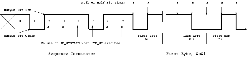 So, to send data out, you just shift it onto the air interface, right? Well, not quite. If you are going to send your data over and over, without being asked for it, you should provide some way for the the listener to know when you are done with one round and starting another. The Atmel 5551 provides a Sequence Terminator (ST) for just this purpose. It's described on page 7 of the datasheet. Typically for RFID, the main feature of the ST is an intentional violation of Manchester timing. The first part of Figure 2 shows the ST sequence followed by the first data bits. If you send this bitstream into your antenna, and put an RFID reader close to your antenna, you will see your data in the RFID reader's output. That leaves only the question of how to modulate or damp the field. Well, LF and HF tags both work through inductance. The air interface is basically a loosely coupled transformer with the reader's antenna as the primary and each tag's antenna serving as a secondary winding (yes, there can be more than one tag present in some protocols - the 5551 supports that to some extent but it's too much to get into here). Your output circuit is a parallel LC tank circuit tuned to 125 KHz. To support modulating the field, you will place a transistor across the tank. When the transistor is off, the circuit is tuned. When the transistor is on, the circuit is detuned, and the air interface is damped. The next figure shows the general scheme with typical component values. 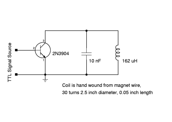 With all the elements in place, we're ready to look at the project. The Sample ProjectThe signal input of Figure 3 is labelled "TTL Signal Source." The source used for this project is a Scenix SX28 prototype board. Listing 1 shows the interesting part of the Scenix program. The full source is available for download at www.circuitcellar.com. Most of the listing is the sample program provided with the SX28 development kit. Everything added for this project is set off by the string "TagEmulator."The Scenix processors are interesting because they have few dedicated peripherals. The Scenix (now Ubicom) designers made a decision to provide a very fast chip with a lot of I/O, so that peripherals could be implemented in software rather than hardware. With clock rates up to 100 MHz, the performance of Scenix processors approaches that of programmable logic. For example, the program as posted still includes the software UART, which bit-bangs RS232 data through any I/O pins you want to use for that purpose. The program's canned output string is at label _RFID_Data. The ISR (label :TE_512Us through :TE_Done where TE stands for Tag Emulator) gets outout bytes from program memory and shifts bits out to the air interface on 512 uS intervals. The interval timing is controlled by the two lines at :rxdone which push the immediate value -163 into the Real Time Clock at the end of the interrupt. That value leads to an interrupt every 3.12 uS, which is important for the software UART timing. To generate the 512 uS intervals for the air interface, code at :TE_512Us checks the value of TE_ClkCnt . When that register counts down to zero, we are at a 512 uS boundary and ready to handle the air interface. One of the first things the code does is to reset TE_ClkCnt to 157 since 157 * 3.12 uS is as close to 512 uS as we could get. The Scenix board has two outputs: circuit common and the transistor's base. The base signal is on port B bit 4. When that signal is low, the transistor is off and the LC tank resonates at its natural frequency. Note that there is no power connection to the tuned circuit - this interface takes almost no power from your project, and only adds noise when an RFID reader is close by. When the transistor base signal is high, the transistor conducts, swamping the tuned circuit. As I said before, neither state is very memorable. But if you carefully change states at the right time intervals, you can create data. 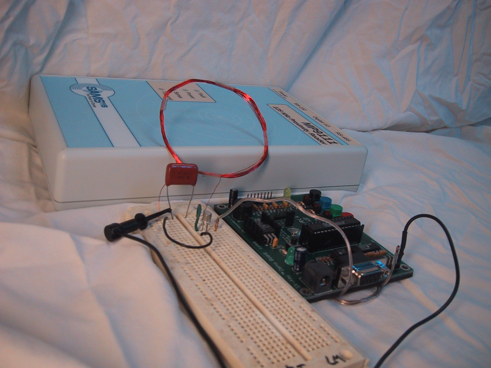 Which is exactly what happens in Figure 4. With the tag emulator circuit running, an RFID reader placed nearby will detect and display your data. Listing 2 is the output from the SAMSys LF reader used to verify my prototype. Listing 2: SAMSys reader output {Rd,d:010101010202020203030303DEADBEEF,t:T128M;04 {Rd,d:010101010202020203030303DEADBEEF,t:T128M;04 {Rd,d:010101010202020203030303DEADBEEF,t:T128M;04 {Rd,d:010101010202020203030303DEADBEEF,t:T128M;04 {Rd,d:010101010202020203030303DEADBEEF,t:T128M;04 {Rd,d:010101010202020203030303DEADBEEF,t:T128M;04 {Rd,d:010101010202020203030303DEADBEEF,t:T128M;04 {Rd,d:010101010202020203030303DEADBEEF,t:T128M;04 {Rd,d:010101010202020203030303DEADBEEF,t:T128M;04 {Rd,d:010101010202020203030303DEADBEEF,t:T128M;04 {Rd,d:010101010202020203030303DEADBEEF,t:T128M;04 {Rd,d:010101010202020203030303DEADBEEF,t:T128M;04 {Rd,d:010101010202020203030303DEADBEEF,t:T128M;04 {Rd,d:010101010202020203030303DEADBEEF,t:T128M;04 {Rd,d:010101010202020203030303DEADBEEF,t:T128M;04 {Rd,d:010101010202020203030303DEADBEEF,t:T128M;04 {Rd,d:010101010202020203030303DEADBEEF,t:T128M;04 MoreWhere to go from here? Well, the sample program would be easy to modify to run, say, RS232 data to the air interface. You could experiment with different data lengths and formats, or cycle your data so that everything you want to say is presented over a set of reader output lines. As you experiment, you may notice that the data coming out of the RFID reader is sometimes different from what you intended. Most RFID tags implement a CRC to keep that from happening. One of the great things about the 5551 is that the tag enforces no CRC, so you can implement readers (and they can implement tags) fairly easily. The downside is that your data has no error protection. Implementing error protection at the application layer would be another fun project.The real adventure will be implementing the forward link, but that will require hardware changes. |